- All
- Product Name
- Product Keyword
- Product Model
- Product Summary
- Product Description
- Multi Field Search


Views: 0 Author: Site Editor Publish Time: 2026-08-03 Origin: Site


Selecting the wrong single-phase electric motor carries serious operational and financial stakes. Equipment stalling under heavy loads, premature capacitor burnout, and excessive energy consumption often stem from one fundamental miscalculation. Many engineers and technicians misunderstand phase manipulation mechanisms. They know both types use capacitors to alter current phase. Yet, they overlook how internal circuitry serves entirely different operating stages. Physical limitations restrict these components to specific duties.
This guide gives procurement and maintenance teams an objective evaluation framework. You will learn to align specific load requirements and environments with the correct motor configuration. Our breakdown clarifies exactly which design fits your industrial needs. We strip away marketing claims to focus on the raw physics of torque, inertia, and electrical efficiency. By mastering these principles, you prevent catastrophic equipment failures before they happen.
Capacitor-start motors deliver high starting torque (up to 300% of full load) but rely on a centrifugal switch to drop the capacitor out of the circuit once operating speed is reached.
Capacitor-run motors utilize a lower-capacitance, continuous-duty capacitor to maintain optimal running efficiency and power factor, but offer limited starting torque.
Heavy-duty, high-inertia applications (e.g., agricultural conveyors, compressors) require start capacitors, while low-inertia, continuous-duty equipment (e.g., HVAC fans, blowers) benefit from run capacitors.
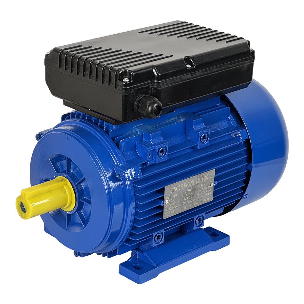
For applications requiring both high starting torque and high running efficiency, dual-capacitor systems (like the YL Series Motor) offer a hybrid solution.
Engineers must understand the physical and electrical distinctions separating these two motor designs. Evaluating a capacitor start vs capacitor run motor requires looking past the outer casing. You must examine the internal circuitry, phase-shifting mechanisms, and component chemistry.
Both motors use an auxiliary winding to create a rotating magnetic field from a single-phase power supply. However, they manage this winding differently. A capacitor-start setup relies heavily on a mechanical or electronic disconnect mechanism. Typically, a centrifugal switch sits on the motor shaft. As the motor accelerates, centrifugal force pushes internal weights outward. When the rotor reaches approximately 75% of its synchronous speed, these weights actuate a spring. The spring opens the electrical contacts. This action instantly drops the start capacitor and auxiliary winding out of the circuit. The motor then continues running solely on its main winding.
Conversely, a capacitor-run motor lacks this disconnect mechanism. It leaves the auxiliary winding and the capacitor energized continuously. The circuit remains closed as long as the motor receives power. This permanent split capacitor (PSC) design provides a constant phase shift. It sacrifices the aggressive starting push for long-term operational stability.
The physical construction of the capacitors dictates their operational limits. Using the wrong type guarantees component destruction.
Start Capacitors: These units feature high capacitance ratings. They typically range from 70 to over 1000 microfarads (µF). Manufacturers design them for short, intermittent duty cycles. They use a non-polarized, electrolytic construction. An internal liquid electrolyte provides massive energy storage. However, this liquid boils rapidly if left energized for more than a few seconds.
Run Capacitors: These components utilize much lower capacitance. Ratings usually fall between 1.5 and 100 µF. They must withstand continuous line voltage without overheating. Manufacturers build them using oil-filled polymer or metallized polypropylene film. This dry-film construction efficiently dissipates constant heat over thousands of operating hours.
Technical features mean little without connecting them to business outcomes and equipment reliability. Motor selection directly impacts mechanical performance and facility energy usage.
Certain machines demand immense "breakaway torque" to begin moving. Hard-to-start loads possess high static inertia. An air compressor pumping against a pressurized tank exemplifies this challenge. A start capacitor provides a severe phase shift between the main and auxiliary windings. This shift creates a powerful, temporary rotating magnetic field. It generates starting torque up to 300% of the motor's full-load rating.
A run capacitor cannot overcome high static inertia. Its lower capacitance generates a much weaker initial magnetic field. If you apply a capacitor-run motor to a heavy load, the rotor stalls. The stator continues drawing locked-rotor amps (LRA) from the grid. This excessive amp draw causes rapid thermal overload. The internal windings will melt if safety breakers do not trip immediately.
Motors operating on continuous duty cycles prioritize efficiency over raw starting power. Run capacitors excel in this territory through power factor correction. In an AC circuit, inductive loads cause the current waveform to lag behind the voltage waveform. This lag wastes energy.
A run capacitor introduces capacitive reactance. This reactance cancels out the inductive reactance of the motor windings. It keeps the motor current closer to being in-phase with the voltage. By improving the power factor, the motor draws less line current. Lower current reduces resistive heating inside the windings. Over a 24/7 operating cycle, this efficiency translates to significantly lower energy consumption and extended insulation life.
Performance Metric | Capacitor-Start Design | Capacitor-Run Design |
|---|---|---|
Breakaway Torque | Very High (200% - 300%) | Low to Moderate (50% - 100%) |
Operating Power Factor | Lower (Runs on main winding only) | High (Continuous phase correction) |
Heat Generation | High during startup, moderate running | Low, optimized for continuous duty |
Mechanical Complexity | High (Centrifugal switch required) | Low (No internal moving switch parts) |
Decision-stage alignment prevents premature failures. Buyers must deploy each type of Single Phase Motor in environments tailored to its strengths.
High-inertia loads absolutely require the aggressive torque of a start capacitor. Common applications include industrial air compressors, agricultural feed augers, heavy-duty pumps, and commercial table saws. These machines resist rotation when powered on.
Follow a simple rule of thumb. Specify this motor type for applications where the equipment starts under a heavy mechanical load but cycles on and off relatively infrequently. The start capacitor needs adequate cooling time between starts. High-frequency cycling damages the electrolytic core.
Low-inertia, continuous-duty loads represent the ideal environment for run capacitors. You will find them powering HVAC blower motors, exhaust fans, centrifugal light-duty pumps, and garage door openers. These machines encounter very little resistance during startup.
The rule of thumb here is straightforward. Use a PSC motor for applications where the initial load is light, but the equipment runs constantly. The fan blade of an HVAC unit spins freely at zero RPM. It only builds aerodynamic resistance as speed increases. The run capacitor handles this gentle curve effortlessly while keeping energy consumption low.
Some industrial applications refuse to compromise. They demand both massive starting torque and highly efficient, continuous running. Heavy fluid processing mixers and industrial woodworking machinery fit this profile. They start under heavy friction but run for hours.
Manufacturers developed dual-capacitor systems to solve this dilemma. You should evaluate the YL Series Motor for these scenarios. This motor houses both a start capacitor and a run capacitor. It utilizes the start capacitor to break static inertia. Once the centrifugal switch trips at 75% speed, it seamlessly transitions to the run capacitor. This hybrid setup maximizes performance across every stage of operation.
Real-world implementation rarely perfectly matches laboratory conditions. Understanding failure modes helps maintenance teams diagnose issues quickly. It also informs better procurement decisions.
The mechanical centrifugal switch represents a single point of failure in start motors. Dust, vibration, and general wear threaten its reliability. Two distinct failure modes exist.
Switch Sticks Closed: If dirt binds the spring mechanism, the contacts never open. The motor reaches full speed, but the start capacitor remains energized. Within seconds, the electrolytic fluid boils. The capacitor will vent violently or explode. The auxiliary winding often burns out shortly after.
Switch Sticks Open: If the contacts corrode or break apart, the circuit remains permanently open. When you apply power, the start capacitor cannot engage. The motor emits a loud hum but fails to rotate. It will rapidly overheat until the thermal overload protector trips.
Run capacitors face different threats. They endure continuous exposure to heat and microscopic voltage spikes. Over time, these factors degrade the metallized film inside the aluminum casing. Many modern run capacitors possess a "self-healing" property. When a minor voltage puncture occurs, the film vaporizes locally to isolate the fault. However, each healing event slightly reduces the overall microfarad rating.
As the capacitance drops below the motor's specified tolerance, efficiency plummets. The motor draws more current to maintain its magnetic field. Operating temperatures rise. Eventually, the weakened capacitor fails to provide enough phase shift, resulting in a stalled motor.
Technicians often cause premature failures by ignoring voltage ratings during replacement. A critical engineering rule dictates capacitor selection. The replacement capacitor must have a voltage rating equal to or higher than the system voltage. It must never be lower.
AC voltage operates in peak-to-peak waves. A standard 230V grid often generates peak voltages much higher than 230V. Therefore, engineers typically specify a 370V or 440V capacitor for a 230V motor. Installing a 250V rated capacitor in this system guarantees rapid insulation breakdown and catastrophic failure.
Use this logical sequence to evaluate OEM datasheets and narrow down your single-phase motor choices.
Determine exactly how your equipment behaves at zero RPM. Is it starting under heavy compression or friction? Does it spin freely like a fan blade? High static inertia automatically disqualifies a standard PSC run-capacitor motor.
Calculate the estimated number of starts and stops per hour. Start capacitors require adequate thermal recovery time between engagements. If your process requires rapid, high-frequency cycling, a standard centrifugal switch mechanism will fail prematurely. You may need specialized electronic switching or a three-phase alternative.
Balance mechanical complexity against operational efficiency. Start motors introduce moving switch parts susceptible to environmental wear. Run motors offer simpler mechanics but lack raw starting power. Evaluate whether the environment exposes the motor to heavy dust or vibration, which threatens internal switches.
Scrutinize OEM datasheets closely. Verify the NEMA frame sizes match your mounting requirements. Check the Ingress Protection (IP) ratings. An IP55 rating blocks dust and water jets, protecting sensitive internal switches better than an open drip-proof (ODP) IP23 enclosure. Finally, demand documented life expectancy metrics for the onboard capacitors.
Your mechanical load at startup and your efficiency requirements during operation strictly dictate your motor selection. Misapplying these technologies guarantees downtime and destroyed components.
Analyze your machine's breakaway torque requirements before looking at motor specs.
Match continuous-duty, low-inertia applications with simpler run-capacitor designs.
Review your torque curves with an engineering specialist if you suspect your load profile fluctuates.
Explore dual-capacitor alternatives for heavy machinery demanding both aggressive starts and smooth continuous operation.
A: No. A run capacitor lacks the required microfarad capacity to generate massive starting torque. It cannot create a sufficient phase shift for high-inertia loads. If substituted, the motor will likely hum, stall, and overheat rapidly.
A: Absolutely not. Manufacturers design start capacitors strictly for intermittent duty, usually lasting less than three to five seconds. Leaving them in the circuit boils their internal electrolyte. They will overheat, vent violently, or burst.
A: Start capacitors usually sit inside black plastic casings due to their electrolytic construction. The motor also produces a distinct mechanical click as it spins down. Run capacitors typically inhabit silver aluminum cans. Dual-capacitor motors feature two distinct humps on the casing.

